Product
EDU
Electric Drive Unit
Low-impedance Solenoid-type Fuel Injector Driver
The EDU is a programmable, universal driver for low-impedance solenoid-type fuel injectors.
Highly reliable and repeatable injections
- High capacity power unit enables high-speed magnetization of the injector. This feature enables highly reliable multi-injection and simultaneous injection among multiple cylinders.
- High-speed current measurement and control technology enables high accuracy injection control. (1µs resolution)
- Supports multiple injection strategies. Enables high degree of freedom for pilot, pre, main, post or other injections.
- Ideally suited to diesel combustion R&D and injection control algorithm development with high reliability, accuracy and repeatability injection profile.
Can be applied to a variety of applications
- Each channel can be configured for different injection profiles independently, which enables the control of a variety of injectors, even from different manufacturers. No need for new injector drivers to operate different engines.
- Individual injection timing can be controlled independently. This enables the testing of various patterns of injection for control strategy development and comparison.
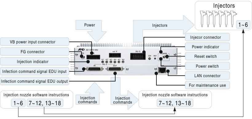
- 1 EDU can control up to 6 channels (injectors).
- Can be extended to 3 units (total 18 channels) with daisy chain communication.
Easy settings of injection profile and onboard memory
- Injection profiles can be set up easily with profile table.
- Injection profile tables can be stored into flash memory inside the EDU device. Loading injection profile data from flash memory enables fast start up for testing and development.
The technology
A&D's analog technology enables high-speed current measurement and high quality control.
Injection profile (current control) setting parameters
(closed-loop current control)
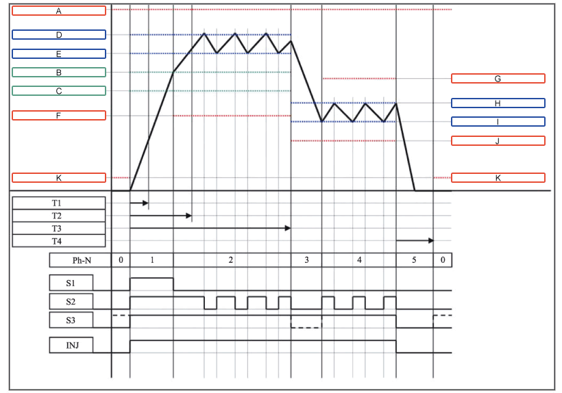
Diesel Engine Control
| Symbol | Name | Description | Value Range Initial Value |
|---|---|---|---|
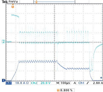
| A | High Current Upper Limit | Valid during the whole period of Ph. The maximum-current value specified through an entire region. If current exceeds this threshold, an error [HC_ULE] is generated and SW status is changed to "excitation current OFF." |
4.00~ 25.00 22.00A |
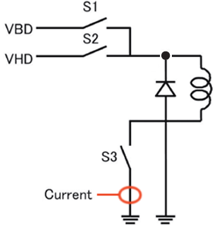
| B | VH High Current Upper Value | Valid during the period of Ph-1 and 2. If excitation current exceeds this value, VH excitation (S1) is turned OFF. |
3.00~ 24.00 10.00A |
| C | VH High Current Lower Value | Valid during the period of Ph-1 and 2. If excitation current drops below this value, VH excitation (S1) is turned ON. |
2.00~ 23.00 7.00A |
| D | VB High Current Upper Value | Valid during the period of Ph-1 and 2. If excitation current exceeds this value, VB excitation (S2) is turned OFF. |
3.00~ 24.00 9.00A |
| E | High Current Lower Limit | Valid during the period of Ph-1 and 2. If excitation current exceeds this value, VB excitation (S2) is turned ON. |
2.00~ 23.00 8.00A |
| F | Low Current Upper Limit | Valid during the period of Ph-2. Allowable minimum value of wave fluctuation during the retention period of a high current region. If current drops below this threshold, an error [HC_LLE] is generated and SW status is changed to "excitation current OFF." |
1.00~ 24.00 6.00A |
| G | VB Low Current Upper Value | Valid during the period of Ph-4. If the maximum value of wave current fluctuation during the retention period of a low current region exceeds this threshold, an error [LC_ULE] is generated and SW status is changed to "excitation current OFF." | 4.00~ 25.00 22.00A |
| H | VB Low Current Lower Value | Valid during the period of Ph-3 and 4. If excitation current exceeds this value, VB excitation (S2) is turned OFF. |
3.00~ 24.00 4.00A |
| I | Low Current Lower Limit | Valid during the period of Ph-3 and 4. If excitation current drops below this value, VB excitation (S2) is turned ON. |
2.00~ 23.00 3.00A |
| J | OFF Current Upper Limit | Valid during the period of Ph-3 and 4. Allowable minimum value of wave fluctuation during the retention period of a low current region. If current drops below this threshold, an error [LC_LLE] is generated and SW status is changed to "excitation current OFF." |
1.00~ 10.00 2.00A |
| K | Rise Time Lower Limit | Valid during the period of Ph-0. Allowable-current value when setting excitation current to OFF. If current exceeds than this threshold, an error [operationality criterion_ULE] is generated and SW status is changed to "excitation current OFF." | 0.30~ 1.00 0.30A |
| T1 | Rise Time Upper Limit | Since the rate of current value change is too large if the rising period (Ph-1) of excitation current is shorter than this, an error [RT_LLE] is generated and SW status is changed to "excitation current OFF." | 10~ 2,000 10µS |
| T2 | High Current Interval Time | Since the rate of a current value change is too small if the rising period (Ph-1) of excitation current is longer than this, an error [RT_ULE] is generated and SW status is changed to "excitation current OFF." | 10~ 2,000 300µS |
| T3 | OFF Current Interval Time | A period excited with high current. If it exceeds this time, the sequence shifts directly to Ph-3. | 10~ 2,000 400µS |
| T4 | Injection Time Lower Limit | During this time SW status changes to Excitation OFF. Excitation current becomes zero in this period. (Set it to take the value of an AD zero sampling.) |
100~ 2,000 800µS |
| T11 | Injection Time Lower Limit | Warning [IT_LLW] is generated if an injection instruction signal is less than this time. | 10~ 2,000 100µS |
| T12 | Injection Time Upper Limit | If an injection instruction signal exceeds this time, injection behavior is stopped directly and a warning [IT_ULW] is generated. | 10~ 2,000 1,500µS |
| T13 | Injection Interval Lower Limit | If an injection indication signal time interval is less than this time, warning [IBM PCN II_LLW] is generated. | 10~ 2,000 100µS |
| T14 | Injection Interval Upper Limit | If an injection indication signal time interval exceeds this time, warning [IBM PCN II_ULW] is generated. | 100~ 13,000 1,000mS |
Diesel Engine Control
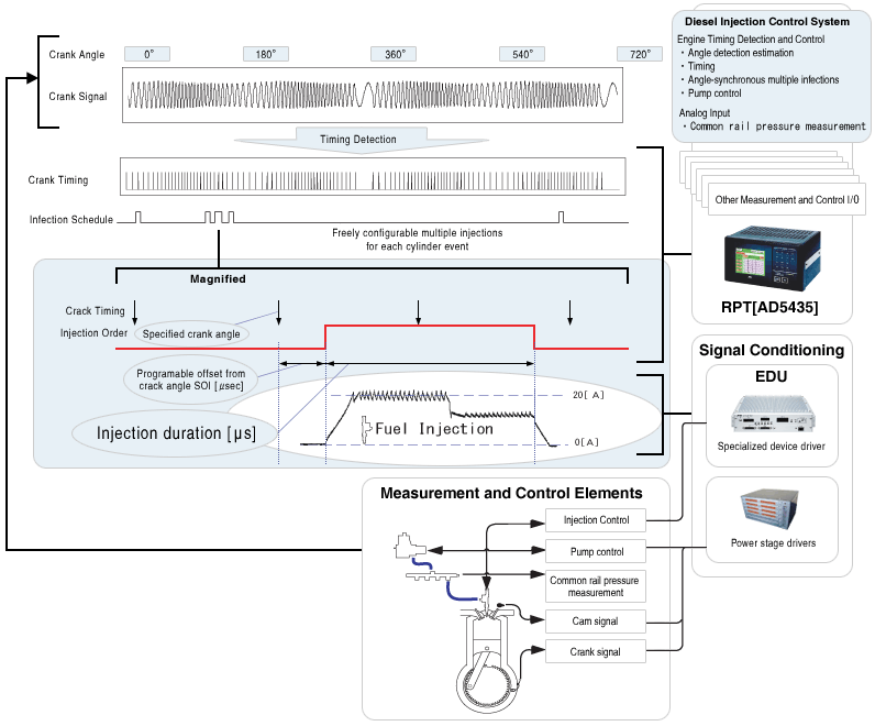
Configuration
The crank angle signal is obtained from the engine.
Injection command signals (timing/duration) are generated from ECU or RPT.
Injection profile (current) is sent and controlled from the EDU.
Detailed injection control settings and commands required for R&D, which could not be obtained from a real ECU, can be realized with the EDU.
EDU specifications
| Model Name | EDU 1x series | EDU 2x series | |||||
|---|---|---|---|---|---|---|---|
| AD5452-EDU10 | AD5452-EDU11 | AD5452-EDU20 | AD5452-EDU21 | AD5452-EDU22 | |||
| Power supply (Input voltage range) |
12V (+8V~+18V)*1 |
24V | |||||
| (+16V~+36V) | |||||||
| Non-destructive input voltage | -32V~+42V | ||||||
| Maximum input current | 20A | ||||||
| Power | VBD | Main chassis supply | |||||
| VHD | Main chassis supply | Internal high voltage supply Configurable range:50V~110V |
Main chassis supply | Internal high voltage supply Configurable range:50V~110V |
Internal high voltage supply Configurable range:80V~140V |
||
| Buttery Input | Control unit | Power Consumption | TYP:5W MAX:6W | ||||
| Standby current | Less than 10mA | ||||||
| Input Impedance | More than 10kΩ(in case of switching to remote mode (RMT)) More than 1MΩ (except switching to remote mode (RMT)) |
||||||
| Remote control function | Standard | ||||||
| Input | Over current fuse protected | ||||||
| Driver | Input | Over current fuse protected | |||||
| VH Power Output | Capacity | 50~100W*2 | 50~100W*2 | ||||
| Output voltage | 50~110V | 50~110V | 80~140V | ||||
| Resolution | Less than 0.1V | Less than 0.1V | |||||
| Accuracy | ±5% of F.S*4 | ±5% of F.S*3 | |||||
| Output Maximum Current | 100A*4 | 100A*2 | |||||
| Ripple | Less than 500mVp-p*5 | Less than 500mVp-p*5 | |||||
| Input | Over-current fuse protected | Over-current fuse protected | |||||
| Output over-current protection mechanism | 1.6A/250µs | 1.6A/250µs | |||||
| Overheat protection mechanism | Standard | Standard | |||||
- *1 Active only in cranking; 10~18V in normal mode
- *2 Depends on output voltage configuration.
- *3 In case of no load.
- *4 Pulse range 100μs intermittent, voltage change less than 5V.
- *5 Range 20MHz and 25℃.
Injector Driver
| System | Current control | |
|---|---|---|
| Number of channels | 6 channels | |
| Injection control signal | 1 line / channel | |
| VH output current | Less than 22A*1 | |
| Current detection | Measurement range | 0~45A |
| Measurement accuracy | ±2% of F.S. | |
| AD resolution | 10 bit | |
| Sampling frequency | 1.25MHz | |
- *1 In case of the following current wave.
General specifications
| CPU | RENESAS SH-2 (SH7055F) processor |
|---|---|
| Communication method | Ethernet |
| Communication device | LANTRONIX X-Port |
| Temperature range | -20~70℃ (non-condensing)*1 |
| Size | 250mm(W)x254mm(D)x73.5mm(H) |
| Weight | 5kg |
- *1 For >45℃, output current derating is necessary.
