Product
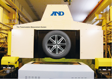
FBTR
Flat Belt Tire Testing Rig
Reproduces any vehicle condition by using six degrees of freedom,
provides realistic road conditions for tire testing through accurate
belt control, measures force precisely with the Model Based Sensor
(MBS), and offers installation flexibility through its compact size.
Features
- Six degrees of freedom enable various tire setups
- Vertical movement (option)
- Belt and Tire are fully driven by electronic motor
- Accurate steel belt control reproduces realistic road condition
- Precise force measurement with the Model Based Sensor (MBS)
- Belt crack detection sensors ensure safety operation
- Compact size
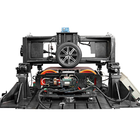
Front view

Tire stand
Crack detection sensor
Six degrees of freedom
A total of six degrees of freedom enable the reproduction of realistic vehicle and road
conditions for tires.
- Flat belt system with belt speed control
- Flat belt mechanics with steer angle control (with dynamic tire stand) and vertical
vibration (option) - Dynamic tire stand with camber angle, tire speed and load force control
- Static tire stand with steer angle, camber angle, tire speed and load force control
All six degrees of freedom can be controlled so that combination tests can be performed.
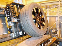
Flat belt system
- The most disturbing aspect of tire testing with a steel belt system is the bending of
steel belt at the tire patch under high load conditions and belt track drift when the tire
generates large side force. The flat belt system is designed to minimize these effects
and reproduce stiff road conditions. - The flat belt system enables various tire slip tests at high speeds.
Flat belt mechanics
- The flat belt mechanics moves the flat belt system and allows dynamic steering of
the flat belt. Vertical vibration movement is also offered as an option. The flat belt
mechanics is used with the dynamic tire stand.
Movement of the dynamic tire stand
- The dynamic tire stand is designed for changing tire conditions dynamically.
- Full braking and spinning testing can be controlled dynamically, reproducing almost
any spinning conditions. - The camber angle can be controlled dynamically. When this control is combined
with the steering control of the flat belt mechanics, almost any dynamic driving
conditions can be reproduced.
Safe operation
- Belt crack detection sensors ensure safe operation.
- Early detection of a crack may make it possible to salvage a damaged steel belt.
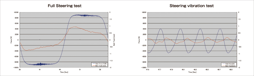
Precise belt control
- The graphs below show that a side force of more than ±8 kN is applied to the belt (The change of force is over 16 kN.).
Even under high load and dynamic changeover conditions, belt track control stays within ±1 mm.
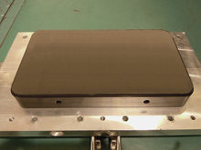
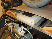
Air bearing
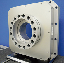
6 component force sensor
Air bearing technology
- The unique air bearing developed by A&D enables the optimum design for the high
load conditions required for tire testing. - The porous carbon material and an optimized airflow path offer the best belt levitation
characteristics. Belt sink under load is less than 50μm. - The air bearing is made of carbon material, which prevents damage to the steel belt
and offers safety and durability.
Precise force measurement with the Model Based Sensor (MBS)
- Shear strain gauges detect shared force at the optimized spring element.
- Gauge signals are directly converted to digital signals and the 6 components of force
are digitally calculated in the real-time DSP system. - The model-based digital signal processing approach minimizes cross talk errors and
achieves world-class measurement accuracy and robustness. Because of this approach,
the sensor is called the Model Based Sensor (MBS).
Compact size
- Belt Size: (W) 1160 mm × (D) 610 mm × (H) 600 mm
- The small and light design reduces the system requirements for hydraulic pressure, which means that the hydraulic pressure source and other onsite equipment can be small. This feature offers increased flexibility during installation and reduced maintenance.
Specifications
| Item | Specifications | ||
|---|---|---|---|
| Dynamic tire testing | Static tire testing | ||
| Belt speed | Standard | -200 to 200 km/h | |
| Option | -300 to 300 km/h | ||
| Tire speed | Standard | Max 1650 rpm | |
| Option | Max 2475 rpm | ||
| Loaded tire diameter | φ500 - 900 mm | ||
| Loaded radius | 220 - 500 mm | ||
| Camber angle movement | Range | ±15 deg | ±5 deg |
| Speed | 5 deg/sec | Static test only | |
| Camber angle movement | Range | ±20 deg | ±5 deg |
| Speed | 50 deg/sec | Static test only | |
| Vertial movement (option) | Range | ±50 mm | Not available |
| Speed | 30 Hz, 300 mm/sec | Not available | |
| Loading force | Drag force (Fx) | ±10 kN | ±10 kN |
| Side force (Fy) | ±10 kN | ±10 kN | |
| Load force (Fz) | 0 - 15 kN | 0 - 10 kN | |
| Force measurement | Drag force (Fx) | Range : ±10 kN, Accuracy : ±0.1% | Range : ±10 kN, Accuracy : ±0.1% |
| Side force (Fy) | Range : ±10 kN, Accuracy : ±0.1% | Range : ±10 kN, Accuracy : ±0.1% | |
| Load force (Fz) | Range : 15 kN, Accuracy : ±0.1% | Range : 10 kN, Accuracy : ±0.1% | |
| Each moment | Range : ±4 kNm, Accuracy : ±0.1% | Range : ±4 kNm, Accuracy : ±0.1% | |
| Loaded tire diameter | Within ±1 mm | ||
| Steel belt size | Standard | 500 mm × 800 mm at effective flat surface | |
| Vertial movement (option) | Belt driving motor | 200 kW | |
| Tire driving motor | 200 kW | 150 kW | |
| Belt crack detection sensors | 3 Eddy current sensors : 2 at the edge and 1 at the center | ||