Product
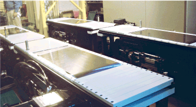
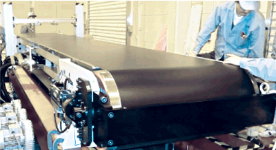
Moving Belt System
Air blow and suction at the rear keep the belt flat using model based control from the DSP system.
Features
- - Model based control by DSP controls air blow and meandering to ensure high accuracy.
- - Air bearings where the tires contact can support full-scale vehicle loads.
- - Special steel belts provide a long operating life at heavy loads.
Specifications
- - Velocity: 230 km/h
- - Surface flatness: within ±0.5 mm
- - Meandering accuracy: within ±0.5 mm
- - Maximum load: 4 tons
- - Belt width: more than 2 m is possible
On-road driving testing on a test bench or in a laboratory
On-road driving testing can be performed on a test bench or in a laboratory using either a rotation roller or a moving belt. Rotation rollers are easy to make and are widely used as low-friction chassis dynamometers for R&D, inspections, and durability tests. However, the surfaces of even large-diameter rollers are round, which means that the area where the tires contact is not the same as a flat road. The surface of a moving belt, however, is like a flat road. Because of this difference, moving belts are often used for tests with severe tire contact conditions and in wind tunnels.
Issues and solutions for moving belt systems
General moving belt systems have many challenges, including belt longevity, meandering control, fluttering suppression, and heavy-load bearing mechanisms. A&D’s latest system overcomes these issues.
Meandering control and fluttering suppression
The plate under the moving belt has air holes that take in and blow out air to suppress belt fluttering. Meandering is suppressed by controlling the left and right tensile forces of the belt pulley. Model based control with a DSP controller ensures accuracy within ±0.5 mm.
Model based control using control object modeling concepts (Simulations can be performed in advance using MATLAB/Simulink)

Meandering control data
Meandering control data (high speed stability)
Fluttering control data (high speed stability)
Data for meandering during actual motion
Pulley Shape Simulation
When designing the shape of the pulley in driving mechanism of a moving belt, increasing the bulge at center of the pulley can decrease meandering volume. However, this produces unnecessary torsion in the belt. A&D determines the optimal crowning radius through simulations of belt materials, width, thickness, length, and so on.
Air bearing mechanism
Air-bering mechanism (Example of double structure 1+2 and moving mechanism)
When a tire contacts the moving belt and subjects it to axial load, the air bearing moves the belt to maintain a consistent gap with the plate below it.
Principles of Air Floatation
The air bearing system uses the principles of air floatation. As you can see from diagram on the right, the air-bearing plate has several air holes that blow compressed air. This action creates an air layer between the plate and the belt. When load is applied to the belt and the gap between the plate and belt becomes smaller, the pressure of air layer is increased. When the load is lightened and the gap widens, the pressure is lowered. This mechanism maintains the constant distance between belt and plate.
Air Bearing Mechanism
A&D has several types of air bearings for different system structures, including a single fixed type and a multiple movable type. Tire testing machines utilize a single fixed bearing plate with the necessary surface area. When using full-scale two and four wheeled vehicles, it is necessary to accommodate the planned test range of the tread or wheel base dimensions. To achieve this, a double bearing plate structure or a moving mechanism, as shown in the diagram on the right, is required.
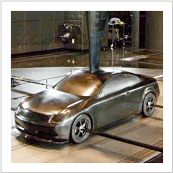
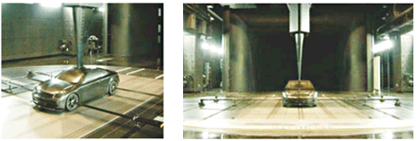
Moving belt for a large wind tunnel (Nissan Technical Center)
A wind tunnel testing machine allows indoor measurement of the air resistance received by a moving vehicle by creating conditions similar to actual driving. To create this environment, the equipment stabilizes the vehicle while a large fan creates airflow equivalent to the vehicle speed and moving belts simulate road conditions at the same speed.
This method is very effective because airflow below vehicle body is close to actual running conditions on a road.
Main specification
| Outer diameter of tire | 400 to 800 mm |
|---|---|
| Steering angle | ±2° |
| Camper angle | ±4° |
| Max. pressure from tire | 1 ton + 0.2 G |
| Max. belt velocity | 100 km/h |
| Control | Load and steering angle controls |
| Component force resolution | 0.1 N |
Moving Belt for Large Wind Tunnel
Main Specification
Four belts under tires
| Velocity | 200 km/h or more |
|---|---|
| Max. withstand load | 4 tons (full-scale vehicles) |
| Belt width | 2500 mm |
| Belt length | 6000 mm |
| Unit weight | About 13 tons |
| Surface flatness | 0.5 mm |
| Belt material | Special steel |
Single belt below vehicle
| Max. velocity | 200 km/h |
|---|---|
| Max. withstand load | 3 tons |
| Belt width | 400 mm (steel) |
| Belt length | 800 mm |
Single belt below vehicle
| Purpose | Supports flow of air |
|---|---|
| Max. velocity | 200 km/h |
| Belt width | 1000 mm (special plastic) |
| Belt length | 6000 mm |
Four moving belts under the tires
Moving belt under the body of the vehicle