Information Library
Measurement Knowledge <Part 1>
1. Are Your Cables Too Thick?
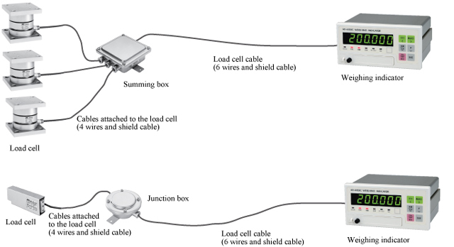
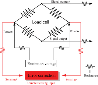
How do people choose load cells cables? If you look around at customers’ factories, you frequently find cables that are thicker than necessary, probably because they are worried about the resistance of the load cell cable causing measurement errors. In the 1970s, it was common practice to choose a cable that was thick as possible to reduce the negative effects of conductor resistance and temperature changes. All of our current weighing indicators have a remote sensing function that eliminates the need for thick cables. Remote sensing monitors changes in the excitation voltage* of the load cell. During A/D conversion, these changes are corrected to offset errors. The cables have six wires, two of which monitor the excitation voltage. Thinning load cell cables cuts costs and we recommend using cables with the optimal thickness to reduce installation costs.
Weighing indicators:
*Excitation voltage: The application of voltage to an electric circuit from another circuit. Here, it indicates the supply of electrical power to the load cell from the weight indicator.
*How to choose the maximum cable length when using remote sensing with A&D’s weighing indicators
2. Getting the Best Performance from Load Cells
Load cells are sensors that output extremely low levels of voltage. When converted to a weighing indicator value, the gradations are often 0.5 μV or less. (This tiny voltage is equivalent to about 1/3,000,000th of that of a battery.) Furthermore, output voltage of the load cell is proportional to excitation voltage. While load cell wiring and connections may appear unusually difficult at first glance, errors can be greatly reduced by observing a few important points. Point 1: Use six-wire cable As was stated above, it is best to use six-wire cable, as the remote sensing function corrects errors due to conductor resistance and other causes. Point 2: Use the shield wire and ground properly(Ground on the weighing indicator side) A shield wire protects the minute output signal of the load cell from surrounding electrical noise. Point 3: Use well-insulated cables and terminals Well-insulated cables and terminals prevent negative effects on the minute output signal. Insulated cables and terminals allow you to maximize the potential of the load cell. We recommend proper load cell wiring for accurate measurement.
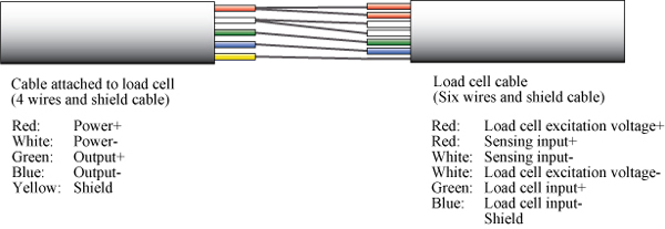
The above shows the wiring relations of the cable attached to the load cell and the six-wire shielded load cell cable. Junction boxes and summing boxes are used to actually connect them. A&D’s junction boxes, summing boxes, and weighing indicators with terminal connections have well-insulated terminals. The optional six-wire shielded cable is also well insulated.
3. Connectors and Contact Resistance
As was mentioned above, electrical noise must be eliminated to achieve the best load cell performance. How are connectors related? The contact resistance of connectors is usually several tens of mΩ. On top of this, the effects of temperature changes and deterioration are large. Load cells output minute analog signals of several μV. Therefore, errors caused by connectors have a large impact on its signal measurements. Naturally, the remote sensing function (of six-wire cables) is effective in this situation as well. The remote sensing function corrects changes in excitation voltage and eliminates most of the negative effects. In fact, even small connectors that can accommodate six-wire cable are more effective in correcting errors than large connectors with low contact resistance.

4. Cautions about Nylon Connectors
As the previous section showed, achieving the best performance from load cells requires attention to connectors. This is particularly true with connectors made of nylon (listed as polyamide, PA66, etc.). Nylon is frequently used in low cost connectors because it is cheap and flexible. However, nylon easily absorbs moisture so humidity can easily lower the insulation resistance. Special attention is required when nylon connectors are used in humid environments and areas where condensation can occur. A fall in the insulation resistance of connectors may cause drift* in the indicator values. If unexplained drift occurs, consider the resistance of the connector.
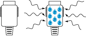
A&D’s connector-type weighing indicators are equipped with high quality metal connectors as standard. *Drift: A condition in which the indicator value does not stabilize and gradually shifts or changes sporadically.
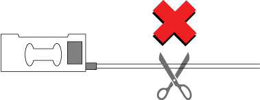
5. Never Cut Cables from the Load Cell
In previous sections, it was stated that load cells benefit from the use of six-wire cables because these cables have sensors that react to the effects of changes in excitation voltage. However, the cable from the load cell is a four-wire cable. Why is this? Temperature alters the resistance of cable from the load cell. If the temperature rises, the voltage applied to the load cell drops and so does the output voltage. So, how is this problem solved? The load cell compensates for temperature changes internally and this includes changes in cable resistance. In other words, the cable from the load cell is part of the load cell. That is why a cable from the load cell must never cut. If the cable is too long, bundle it near the load cell.
